Applications
LoRa Radio Module
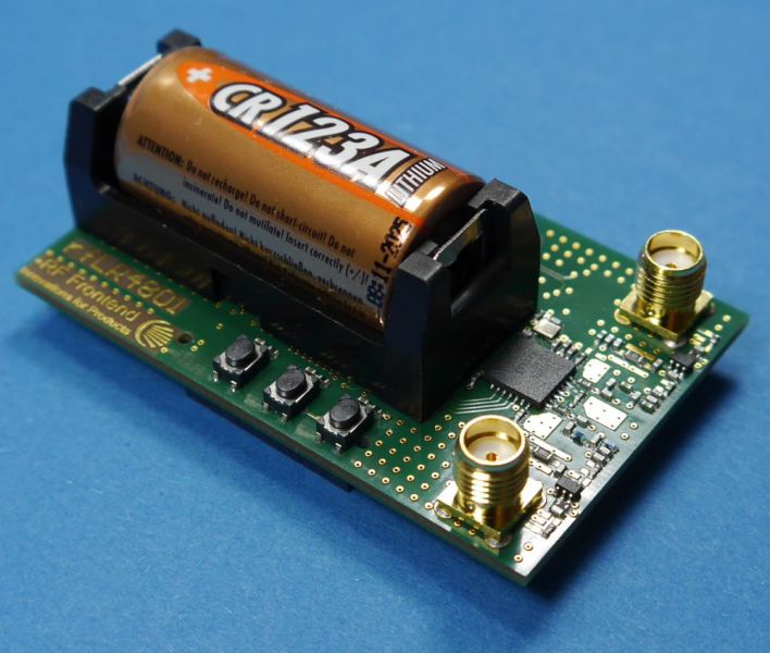
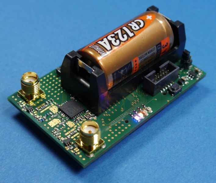
RF-Frontend has developed an universal evaluation Radio Module based on LoRa® techology. You can use this module to check radio coverage in your particular application.
The Radio Module comprises a micro controller where the radio protocol is impletented and a two band LoRa® transceiver. With the two band capability immunity to interference is improved.
It can be used as an autonomous module or integrated into your application circuit using the interfaces of the module. Power can either be supplied with the integrated battery or using USB-power. Of course a laboratory power supply can also be used.
Possible applications are:
- Smart home
- Automatic meter reading (heat and water consumption)
- Wireless alarm system
- Measurement and control in industrial production
- Vast sites like solar and wind parks or agricultuture
The radio Module comes with two rod antennas connected to the two SMA plugs on the module.
Custom specific solutions for radio modul form factor, antennas or the radio protocol can be provided on request.
ARM Cortex-M programming, STM32

RF-Frontend provides a flexible solution for sensor applications based on the ARM® Cortex® microcontroller (STM32 Cortex M4). Signal sampling, processing and post-processing of the measured data is all done on one board. The software can be adapted to different measurement applications.
A total number of 12 analog inputs is provided; since 3 ADC are implemented 3 of these inputs are sampled simultaneously. This is especially important for aplications, where the phase difference of different signals is measured with high precision (e.g. 3-phase systems). Resolution and sampling rate of the ADCs are up to 12 bit and 2.4 MSps. Samples data is directly transferred to main memory via DMA so that sampling and processing is done in parallel.
The Cortex® MCU provides DSP functionality like FFT, FIR and IIR-filters; interfaces for configuration and data IO are UART, SPI and Ethernet.
LTE bandpassfilter for lab applications
In rural areas or under conditions with limited reception, the regeneration of weak signals is required for a stable mobile phone connection. For this purpose, two-way amplifiers (up- and downlink), also called repeaters, compensators or boosters, are often used as relay stations.
FCC Part 20.21 specifies a number of requirements for these devices to minimize interference with other wireless networks. Some of these measurements require frequency limiting using bandpass filters and/or notch filters to measure the specified measurement signal in the presence of a (strong) interfering or wanted signal.
Typically, adjustable filters based on coupled, tunable cavity resonators are used for this purpose. These filters are unwieldy, expensive and require a significant amount of time and appropriate measuring equipment to tune to the desired frequency range and the required filter characteristics.
For testing of, for example, the oscillation tendency of an amplifier or booster (§20.21(e)(8)(ii)(A) Anti-Oscillation), a setup as shown in Fig.1 is typically used.

For our partner CETECOM Essen, a set of high-quality measurement filters was developed as a low-cost, robust alternative in the laboratory for convenient use during the development phase of the devices (Fig. 2). The frequency ranges covered are listed in Table 1.

| Band | Uplink | Downlink |
| 2 | 1850 MHz – 1910 MHz | 1930 MHz – 1990 MHz |
| 4 | 1710 MHz - 1755 MHz | 2110 MHz - 2155 MHz |
| 5 | 824 MHz - 849 MHz | 869 MHz - 894 MHz |
| 12 | 699 MHz - 716 MHz | 729 MHz - 746 MHz |
| 13 | 777 MHz - 787 MHz | 746 MHz - 756 MHz |
Tab. 1: Frequency table for LTE bandpassfilter
The filter characteristics and the maximum input power vary depending on the components used. Murata SAW duplexers are used to provide the input power required for the vibration tilt tests, which are specified for an input power of +29 dBm. The unused connector of the duplexer is terminated with 50 Ohm.
These filters are enclosed with a robust aluminium housing to be used conveniently in the laboratory. SMA connectors on two opposite sides of the housing allow the filter to be changed easily and thus quickly adapted to the required frequency range. The filter description milled on the housing cover is abrasion-resistant, allowing clear identification of the filter even after years of use.
If required, filters and duplexers for other frequency ranges can also be implemented at short notice.
The filters can be ordered individually or as a complete set from CETECOM or from us.
PCB prototype production

We manufacture multilayer PCBs with professional standard in our own PCB laboratory for our development team and for the customers as per requests. Vias are galvanised the surface is gold plated and can be used for bond wires.
Redesigning / board layout modifications of PCBs are only a matter of hours for our engineers.
This fast and efficient approach makes us unique among all others and provides excellent results for the customers.
Available PCB substrates include FR4 and RF materials (e.g. Megtron, Rogers, as well as FlexPC, also in mixed configuration).

RF circuits are very sensitive to the specific PCB matrial used. Therfore, we are using the same material (core, prepreg) as will be used in volume production. This avoids tuning and redesign steps in late in the project.
Boards can be finished with solder mask to simplify prototype production.
The layout data is generated either by our in-house layout tools (Altium Designer, Eagle) or can be provided as Gerber or DXF by the customer.
Overall quality and precision is comparable with volume manufacturers.
Driver amplifier for RF-Heating applications, 10 Watt at 915MHZ

CW-capable driver amplifier for 915MHz with output power of 10W
RF connector to PCB transition

Transitions from coaxial connectors such as SMA, SMB, MCX or N connectors to a microstrip or stripline must be designed with low matching losses.
It is often necessary to optimize the structure or layout by field simulation of the transition. This is typically done by a simulation in CST program.
Since the transition is also subjected to mechanical stress, the mechanical connection of the plug or socket must be designed accordingly for robustness.
Usually, test boards are created first, on which the verification and optimization in the time and frequency domain (TDR measurement, S-parameter measurement) are performed. Measurements up to 40 GHz or 25ps time resolution can be performed in-house.

The figure on the right shows the design of an SMA to stripline transition. For good mechanical stability the connector is soldered all around to the PCB.

The measured values show a matching of better than 20dB up to over 12GHz, and a matching of better than 25dB is safely reached up to 10GHz. These are accomplished with an inexpensive, standard connector.

The deviation in impedance from the target impedance of 50 Ohms is less than 2 Ohms. This makes the connector transition suitable for more demanding measurement applications. In principle, a good SMA to microstrip transition can also be achieved in a similar way.
Automotive Ethernet (BroadR-Reach)
Data transmission using the BroadR-Reach automotive Ethernet standard in automobile applications is under different requirements compared to standard 100BASE-TX Ethernet. The 100BaseT1 and 1000BaseT1 standards were created for this purpose. Although these are standards for digital data transmission, their implementation in components requires detailed knowledge of radio frequency technology. Important parameters of the standard are typically high-frequency characteristics such as matching and overcoupling. Since the transmission is differential to reduce interference sensitivity, the mode conversion of components is still an important and critical parameter.
The properties are also partly specified by TDR measurements.

RF-Frontend has extensive experience in the development of components for the Automotive Ethernet standards. Differential measurements can be performed in both time and frequency domains. Components can be measured with a rise time of 25ps.

The figure on the right shows the measured reflection of the common mode signal when excited with a push-pull signal (mode conversion). To achieve the very low values of measured mode conversion, the signal path has to be designed as symmetric as possible. Special requirements are also placed on the measurement technology, as even the phase change of simple measurement cables can result in measured values that are outside the specification.

This figure shows the measured adjustment of the push-pull signal. Besides the adapted design of all microstrip or stripline lines on the board, a low-reflection design of the transitions to the connectors and the twisted-pair cables is necessary.
 of an evaluation baord for Automotive Ethernet connectors")
The measurement of matching in the time domain is done by a TDR measurement. Here a push-pull signal is applied to the circuit, the reflection is measured over time and converted into impedance. This type of measurement has the advantage that the individual reflections are resolved in time and space.
")
The figure on the left shows the measured overcoupling of a push-pull signal to an adjacent differential line. This type of overcoupling is called NEXT (Near-End-Cross-Talk) or FEXT (Far-End-Cross-Talk). A network analyzer (NWA) with 2 differential ports or a 4-port NWA is required for this measurement.
Automotive Ethernet, power over dataline (PoDL)
 evaluation board")
In many applications requiring the connection of terminal devices to the Internet via Ethernet, electrical supply is partly supplied from the central switch via PoE. This eliminates the need for multiple decentralized power supply units.
Particularly for data transmission in automobile applications via the related standards 100BaseT1 and 1000BaseT1, it is reasonable to transmit the supply power via the signal lines. This way, separate supply lines can be avoided and ultimately the total weights are reduced.
RF-Frontend has developed an evaluation board that converts the standard Ethernet 100BaseT to the automotive standard 100BaseT1, which at the same time enables power coupling into the 100BaseT1 path. Firgure 1 shows a 3D representation of the mentioned board. The relevant parameters of the 100BaseT1 standard are maintained with sufficient reserve. Figure 2 shows two important measurements.
Measurement results
The following figure shows the mode conversion and mactching values of the 100BaseT1 PoDL Evaluation Board

Testing the PoDL boards with data
Two of these evaluation modules can be conencted into a standard Ethernet line to verify the data transmission. A direct current of 500mA can be transmitted, and the direct current resistance is less than 2Ohm. The following figure shows a corresponding test.
Higher currents of up to 2A are possible and have already been realized in the laboratory setup.
