For-Schleife
Der folgende Modul ist erforderlich für die For-Schleife in Node RED:
node-red-contrib-loop-processing
Man kann den installieren, entweder in Command Line mit Befehl „npm install node-red-contrib-loop-processing“ oder unter „Menu->Palette Verwalten->Installieren“ den Modul suchen
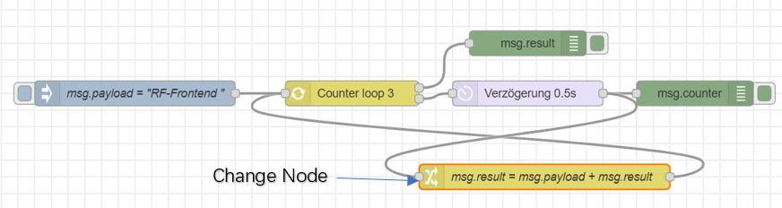
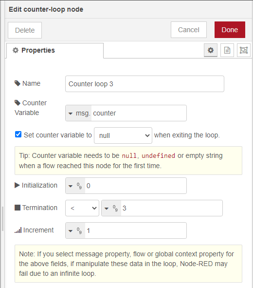
Diese Konfiguration ist gleich in der Programmiersprache Java oder C „for(int counter=0;counter<3;counter++)“.
Der Ausdruck „Counter<3?“ wird als boolescher Ausdruck ausgewertet. Falls der Wert false ist, wird die For-Schleife beendet.
Wenn „Set counter variable to null when exiting the loop” ausgewählt ist, wird Counter nach der Schleife annulliert. Dies ermöglicht, mit ein Counter mehrere Schleifen aufzuzählen.
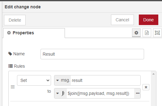
Im Knoten „Change Node“ ist die Veränderung aller Variablen durchzuführen, aber bitte achten darauf, dass das Counter dabei NICHT verändert werden sollte.
Die String-Verarbeitung in JavaScript ist etwas anders als in Java oder C++. Zur Addition von Strings bitte den Befehl „$join([String1,String2])“ benutzen.
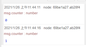
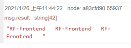
Das Programm ist so konfiguriert, dass die Variable „msg.counter“ mit jeweiliger Ausführung der For-Schleife im Debugging-Fester ausgedrückt wird. Anschließend wird die Variable „msg.result“ dagegen am Ende der Schleife einmalig ausgedrückt.
Finden Sie das Gesamtprogramm unter dem folgenden Link
https://github.com/wuchenthomas/For-Loop-Node-RED/blob/main/ForLoop
Smart power plug reprogramming (friendly guide)
[all used source code and documents can be found on github: https://github.com/aharby/oven_controller]
In this project we are going to reprogram a smart power plug, which built on esp8266, to be controlled from board, Arduino with wifi-module or another esp8266 board.
That could be useful for
- privacy reasons, so you don’t want your data to be sent back and forward to a server based in somewhere on Earth.
- Safety critical applications, that was a main aim for us. So we have an application that deals with high temperatures and want our power plug relay to be safely controlled from a distance.
Our project consists of two boards, one for the power plug relay and the other is for control. They communicate through a protocol called espnow
the control unit has 3 elements to control the relay:
- temperature control
- timer
- manual switch
Components
- Smart power plug (esp based)
- Esp-NodeMCU board
- 16x2 lcd (with i2c interface)
- Keypad
- I/O expander (Pcf8575)
- Temperature sensor (max6675 with thermo coupler)
- Usb FTDI cable
- Arduino IDE installed on your machine
Prerequisites
Arduino IDE
In this tutorial we are using Arduino IDE to program our esp boards.
Follow this guide to be able to execute your program on esp8266 board using Arduino IDE program.
Esp now
ESP-NOW is a protocol developed by Espressif, which enables multiple devices to communicate with one another without using Wi-Fi. The protocol is similar to the low-power 2.4GHz wireless connectivity that is often deployed in wireless mouses. So, the pairing between devices is needed prior to their communication. After the pairing is done, the connection is secure and peer-to-peer, with no handshake being required.
Example: code on our esp8266 power plug
The code is fairly readable and easy to understand.
We have to struct messages in and out, which should match the peers on the other board. Also you need to give the mac address of one board to the other, see next section.
Finally there are two call back functions that are being called at every iteration of the loop to exchange data.
Get esp macaddress
Espnow protocol requires the mac addresses of the communicating board. So you need to get the mac address of each board and then use it on the program of the other board to establish the communication.
Run this code at each board to get the mac addresses and save them in a text document.
I2C port address scanner
In order not to waste the I/O pins of the ESP board, we use the keypad and LCD on the I2C bus. Each device should have different I2C address so that the data transfer occurs correctly.
Execute I2C port scanner on the control board after setting up the hardware.
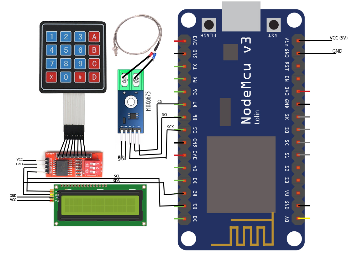
hardware setup
1.Main Board
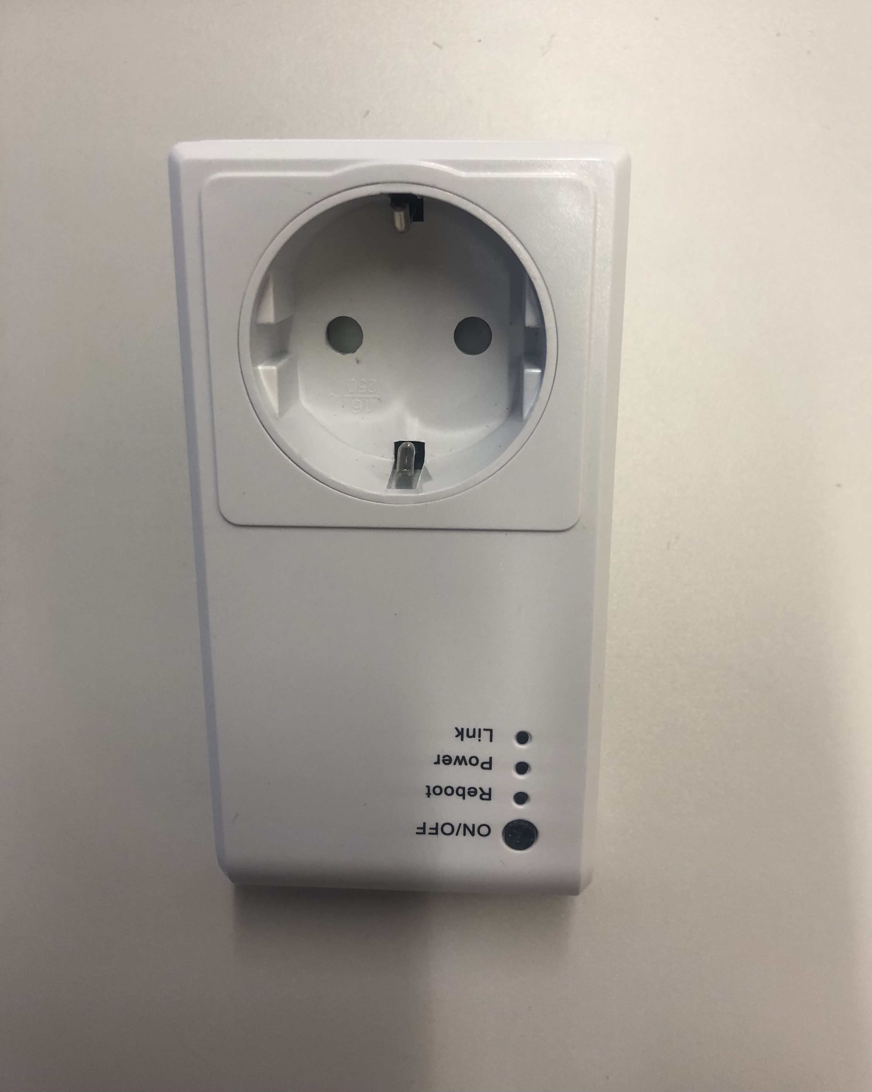
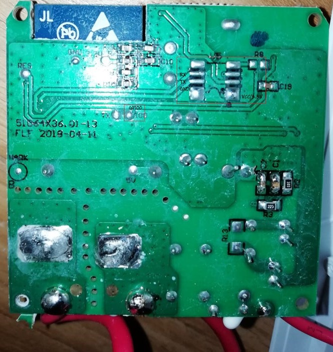
2. Power plug board
2.1 disassembly
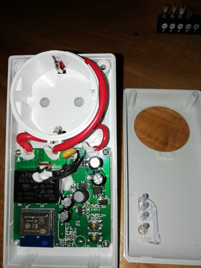
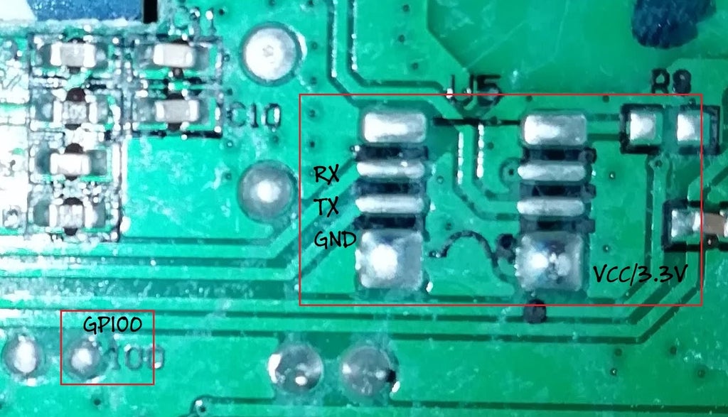
2.2. board important pins
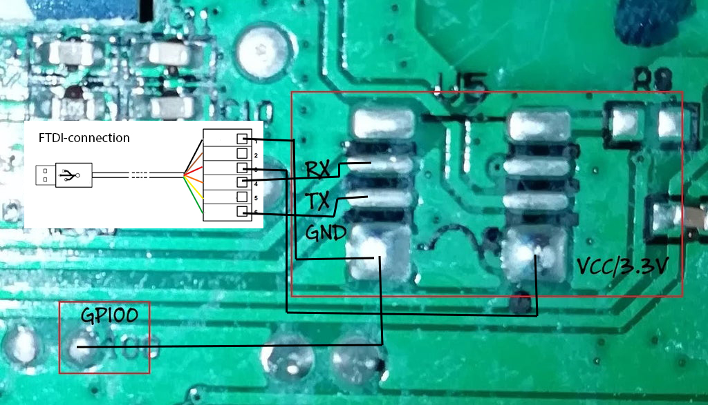
2.3. connection with FTDI
Controller
User can control the power plug from the main board, which is provided by keypad entry and lcd display interface.
Control parameters are being – manual switch – timer control – and temperature control
All user interface including the timer programming is being handled in DisplayHandler class. It is broken down explained in the following section.
Display controler for smart power plug
This module lets us interface power plug through lcd display and keyboard, as well as adds additional control features like programmable timer. Following is the quick overview of methods and features of the module:
Keypad
Keyboard module allows user to interact with power plug without using wi-fi client. Following is the instruction set for possible keyboard commands:
- "A" (timer mode) - start/stop timer
- "B" switch between timer and temperature mode
- "C" switch between display (allows user to see current data) and control (allows user to set timer and temperature limit values) modes
- "D" (display mode) - manually turn the relay on/off
- "D" (control mode) - save current user input and exit control mode
- "*" and "#" (timer control mode) - allows user to move cursor left and right respectively
- "*" (temperature control mode) - deletes the last digit of current temperature threshold and moves cursor accordingly
- "0-9" (control mode) - possible inputs for timer/temperature threshold values
LCD
LCD displays all relevant information to the user and switches between four main modes - temperature display mode, temperature control mode, timer display mode and timer control mode. Temperature display shows current temperature sensor reading and state of relay. Temperature control shows current user input for temperature threshold. Timer display shows on/off state of timer and its current time value. Timer control shows time value being changed by the user.
Timer
Timer functionality allows user to schedule the power plug to turn off after a specified period of time. It is set in hh/mm/ss format and automatically takes care of correctly transforming the changing time values and limiting user input. Timer is set in timer control mode and can be turned on/off with A button.
Temperature limiter
Users can set a maximum temperature value through the temperature control mode. Upon reaching this threshold in temperature sensor readings, power plug will turn off.
Final code
Main Board
use the code under this link. Note that you need to have the whole folder, then open esp8266_controller.ino file and upload.
Power-plug Board
Where to look for more?
https://randomnerdtutorials.com/esp-now-two-way-communication-esp8266-nodemcu/
https://www.instructables.com/OBI-Wlan-Steckdose-Version-2-ESP-WROOM-02/
Abanoub Harby
[email: methany@rf-frontend.de]
Kyrylo Zartovskykh
[email: Zartovskykh@rf-frontend.de]